| (1). Turnoff the power, remove the floppy disk drive.
(2). Install the FDD-UDD on the floppy disk drive local, connect with the 5V power wire and34-pin data wire which are used by the former FDD. Connect power wire first, connect thedata wire later. And remove data wire first, power wire later.
Connection of power wire: connect the 5V power wire in device to FDD-UDD power wire.In generally, the yellow wire is outside, red wire (VCC) is inside, black wire (GND) is in themiddle. If the power wire is contrary, the chip in FDD-UDD maybe damaged.
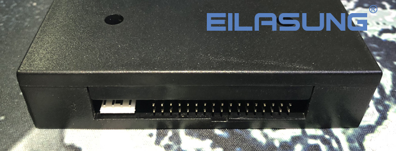
Connection of data wire: connect the 34-pin FDC used by the former FDD to 34-pin data wire in FDD-UDD. The data wire bulgy slot in FDD must match with groove slot in FDD-UDD. If the data wire is contrary, the FDD-UDD can’t work and even the chip will destroy. When the data wire is contrary, the red light is on while there is no USB Flash Drive is inserted.
(3). Turn on the power. The indicate light L1 (green light) on the front panel of FDD-UDD is bright, and the L2 (red light) isn’t bright; the numeric LED display C.4., waiting to insert the USB Flash Drive. If the numeric LED display EX, it is abnormal. When abnormity, please check the data wire and power wire. If the 34-pin FDD data wire are straight connect wire (the 34-pin FDD data wire in common PC have seven wires are contrary) or the machine has the characteristic, after connection, the red light will light, modify the jumper of J1 and J2 in the FDD-UDD internal. The jumper is in the 2-3 pin of J2 in default. Change the jumper until the FDD-UDD work normally: the red light doesn’t light when there is no operation, and when operation the red light is light. |