|
Note: Please pay much attention on the words with underline.
1. Summarize
With the floppy drive and floppy disk decrease, the equipment which have to use them are facing a rigorous problem, at this time the FDD-UDD present to our sight. It is compatible to the floppy drive’s interface, consumer can make use of it by connect the FDD-UDD to the computer,let the USB Flash Drive to instead of floppy disk, avoiding a great deal of defects the floppy disk has. For mainboard, it is similar with the traditional floppy drive, insert the 34 pin FDC on mainboard, it can be used as the floppy drive, and the application software is no need to modify.
For consumer, actually their use is USB Flash Drive but not floppy disk, compare the USB Flash Drive to floppy disk, the USB Flash Drive has a lot of advantage such as: smaller, carry easily,more length of service, diamagnetism, mould proof and aseismatic.
2. Feature
(1). According with the common 3.5 inch floppy drive criterion, the connection and the use are both the same as the common floppy drive.
(2). Use the single 5V power, for outside is the 34 pins floppy drive interface, which can be connected to the FDC on mainboard through standard floppy drive data-wire.
(3). Support the PC, industrial equipment, embed system and MCU, operated on floppy disk mode by FDC control chip.
(4). In theory, support several operating systems and BIOS which the floppy drive can support,and the software is no need to modify.
(5). Support the USB Flash Drive induct operating system (simulate the startup function of floppy disk, and should allow the floppy disk startup in CMOS).
(6). The capability for USB Flash Drive is no restrict, but it is influenced by floppy disk criterion.
(7). For the influence from floppy disk criterion, since the read-write rate of USB Flash Drive is similar to the floppy disk, the dispersion is no more than 10%.
(8). SFD is the same with common floppy drive which can’t support insert and pull out with power,but the USB Flash Drive itself can support it.
(9). Support the write-protect of USB Flash Drive itself, and the effect is the same as common floppy disk.
(10). Support A disk and B disk , system can have more than one SFD or common floppy drive or even the mix at the same time.
(11). Support the format similar to the common floppy disk , offer the special format tool under the WINDOWS at the same time.
3. The explain and picture for front and back panel
(1). Front panel

Figure 3-1 STD
L1: green light: error indication light. Distinguish the error by the speed.
L2: red light: work indication light. Bright means the FDD-UDD is working.

Figure 3-2 EX, COM
L1: green light: power indication. Bright means power on.
L2: red light: work indication. Bright means FDD-UDD is working.
Numeric LED: display the production type when there is no USB Flash Drive inserted. It is abnormal when display EX .
When it is working normal after inserting USB Flash Drive, the numeric
LED display the number of disk, 00 is default, the button of K1 and K2 can change the number of disk from 00 to 99 .
K1: turn to the next. Turn to the next between 00-99 and the new function.
K2: turn to the former. Turn to the former between 00-99 and the new function.
Note: when the L2 (red light) is bright, means the driver is busy, don’t pull the USB Flash Drive out or carry out any other operation.
(2). Back panel
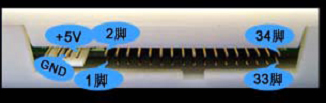
Figure 3-3 STD, EX and Com
Power wire interface: Use +5V power, the red wire (VCC) is internal, black wire (GND) is in the middle. If the power wire is contrary or the voltage is too great,maybe the chip in the FDD-UDD will be destroyed.
Data wire interface: use the former FDD 34-pin data wire, 1-pin is in the left and the 34-pin is in the right. If the data wire is contrary, the FDD-UDD can’t work normally even the chip will be destroyed. If the data wire is contrary,the red light is bright when there is no USB Flash Drive inserted.
4. Jumper inside
(1). Drive selection
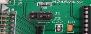
Figure 4-1 J1, J2
There are four choices:
J1 1-2 short connect
Or J1 2-3 short connect
Or J2 1-2 short connect
Or J2 2-3 short connect
The driver is J2 2-3 short connect in default.
According the fact to modify the jumper.
(2). Ready signal selection
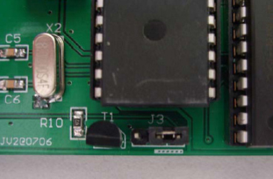
Figure 4-2 J5
There are two choices:
J5 1-2 short connect active with high-level
J5 1-2 cut active with low-level
The ready signal is J5 1-2 cut in default.
According the fact to modify the jumper.
Note: Before the 2B version, customers who connect 1-2 of J3, please connect 1-2 of J5 after using the 2B version and the higher version.
5. The method for using
Connect the FDD-UDD (according the “Usage Manual”), then turn on the power.
If the USB Flash Drive doesn’t insert, the system state supervise will start automatically, and the FDD-UDD will go to sleeping, the drive display no disk. For the STD version, L1 (green light) and L2 (red light) aren’t bright. For the EX and COM versions, L1 (green light) is bright, L2 (redlight) isn’t bright, the numeric LED display the current product type. The FDD-UDD is ready,waiting to insert the USB Flash Drive.
After inserting USB Flash Drive, the system state supervise will identify automatically, the driver work state will be activated. First the driver check itself (including USB Flash Drive check),it will report error when there is something wrong: the STD L1 (green light) glitter with different speed, quick or slow; the EX and COM numeric LED display EX. If there is no error, the L1 (green light) of STD will glitter once a time then extinguish; EX numeric LED display C4, then change to 00; COM numeric LED display C.4., then change to 00, The USB Flash Drive is ready,waiting to operate.
When the host accessing to the drive, L2 (red light) is bright. Make sure don’t pull out the USB Flash Drive when the red light is on or just off in 1 or 2 seconds, otherwise the data write will be error.
The USB Flash Drive used for STD and EX edition, should be format before the first use, the detail method can consult the “Usage Manual-STD” and “Usage Manual-EX”.For COM edition, USB Flash Drive don’t need to format, but need to create file. The FDD-UDD will automatically check and create one file folder UFDDD00, the detail information can consult the “Usage Manual-COM”.
For STD, one USB Flash Drive corresponds as one floppy disk.
For EX, one USB Flash Drive corresponds as 100 floppy disks.
For COM, one USB Flash Drive corresponds as 100 floppy disks, the spare can be used by yourself.
6. Classify
Standard edition:
FDD-UDD STD support 1.44MB one USB Flash Drive corresponds one floppy disk
Excellent edition:
FDD-UDD EX144 support 1.44MB support 100 dummy floppy disks
FDD-UDD EX720 support 720KB support 100 dummy floppy disks , customize program
FDD-UDD EX120 support 1.20MB support 100 dummy floppy disks , customize program
Com edition:
FDD-UDD COM support 1.44MB support 100 dummy floppy disks , the USB Flash Drive no need to format.
7. Applicability
Used for replace the common floppy drive in various area such as: computer, industrial equipment, embed system, spin equipment, embroider equipment etc. |